


Products
-
-
Raw billets, beam billets, and plate billets are lifted using electric lifting magnets.
-
Specialized Lifting Electromagnet for High-Speed Wire (Coil)
-
Pipe blanks, steel pipes, large round blanks for lifting with electric lifting magnets
-
Heavy rail, steel pipe lifting with electric lifting magnets
-
Medium-thick steel plate lifting with electric lifting magnet
-
Medium-thick steel plate multi-sheet lifting special lifting electromagnet
RELATED INFORMATION
Long-term locked-rotor torque motor-type cable reel
The JM□D series of long-term locked-rotor torque motors for cable reels are widely used in large-scale mechanical equipment requiring linear motion, such as bucket-wheel stacker-reclaimers, portal cranes, ship-loading machines, container cranes, and tower cranes. The power source and signal source are located at the midpoint or end of the travel range, and power and control signals are transmitted via the cable reel's cable winding and unwinding actions.
Classification:
E-mail:hnyysg0730@163.com
Case Details
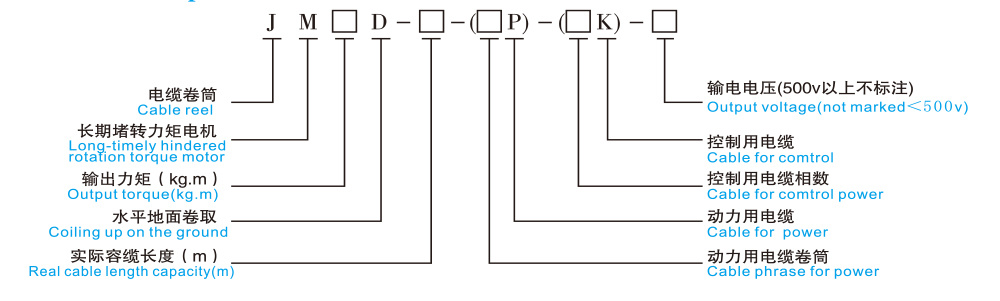
Model Description
Host
1. Power Section
Long-term locked-rotor torque motor (with brake), dedicated gearbox (unit), and collector slip ring box.
Parameters of the long-term locked-rotor torque motor [For reference only]
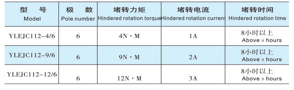
Electrical Parameters and Characteristics of Long-Term Locked-Rotor Torque Motors
1.1 The tension remains constant as the cable moves from an empty reel to a full reel, making it suitable for applications involving long-term low-speed operation with frequent forward and reverse rotations.
1.2 Unlike conventional motors, this motor has a small locked-rotor current and can withstand prolonged locked-rotor conditions and reverse rotation.
1.3. Before assembly, a locked-rotor test lasting 8–10 hours was conducted. The motor temperature rise was less than 65 K, and under hot conditions, the reduction in locked-rotor torque remained within a range of 5%.
Torque Motor Brake Diagram
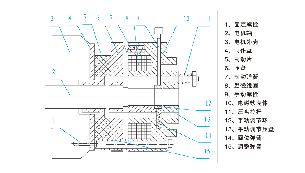
The brake consists of a magnetic yoke, an excitation coil, a spring, a brake disc, an armature, a gear sleeve, a manual release mechanism, screws, and other components.
The brake is mounted on the rear end cover of the motor. Adjust the mounting screws to achieve the appropriate air (or gap) clearance. The motor’s transmission shaft is connected to the brake disc via a gear sleeve.
When the excitation coil of the brake is connected to its rated voltage (DC), the electromagnetic force pulls the armature, causing it to disengage from the brake disc (releasing the brake). At this point, the motor shaft drives the brake disc to rotate normally. When the motor is de-energized, the brake is also simultaneously de-energized. At this moment, the spring presses against the armature, forcing the brake disc to generate a frictional torque against both the armature and the flange plate, thereby bringing the motor shaft to a rapid stop.
2. Power (Signal) Transmission Section
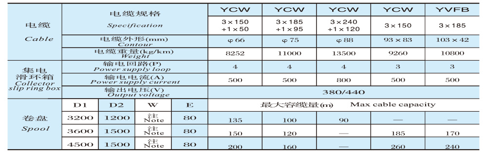
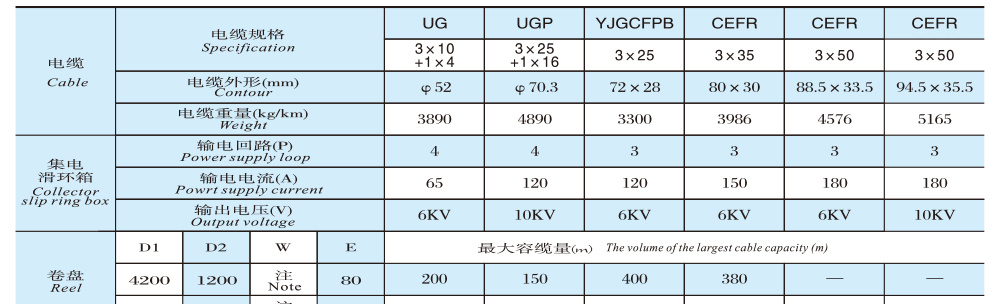
Collector slip ring boxes can be classified according to their purpose into power transmission and signal transmission; and according to voltage levels, they include 220V, 500V, 3kV, 6kV, 10kV, and others.
II. Cable Accommodation Section
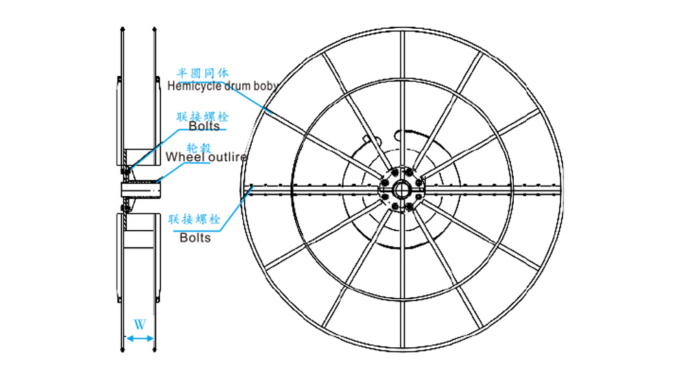
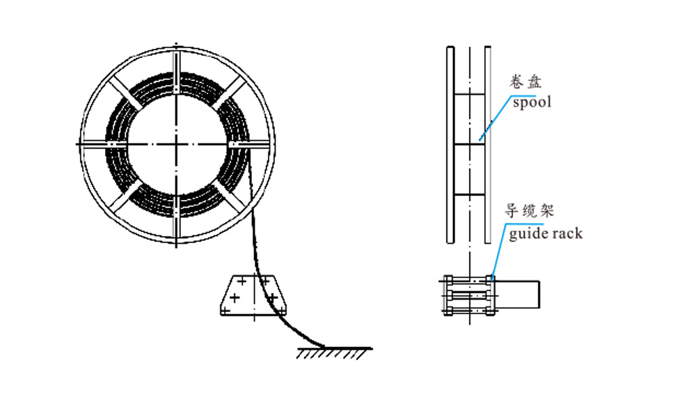
Reel: Reels can be categorized into multi-row winding and single-row winding. For ease of transportation, reels with diameters ≤3m have an integral structure; reels larger than 3m are assembled components that are put together on-site.
Assembly Diagram of the Reel
III. Cable Guide Bracket Installation Diagram
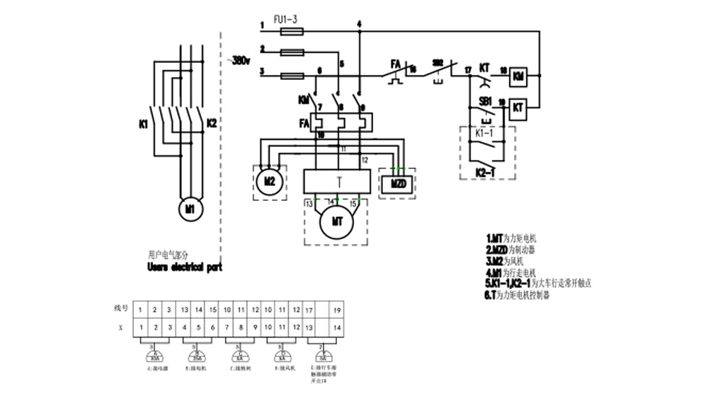
 4. Electrical schematic diagram of the cable reel
Long-term locked-rotor torque motor-type cable reel
Working principle
In cable reels driven by long-term locked-rotor torque motors, both the power transmission and speed-control components are handled by the motor itself. This type of motor possesses unique electrical and mechanical characteristics. It features a wide speed-regulation range and relatively soft mechanical characteristics: when the load changes, the motor’s operating speed adjusts accordingly—increasing load leads to a decrease in speed, while decreasing load results in an increase in speed. Moreover, the motor can operate stably and continuously at any point along its torque-speed characteristic curve, thereby ensuring that the cable maintains an appropriate winding speed and tensile force at the corresponding radius on the reel.
1. Cable winding: The motor’s output torque serves as the driving force, which, through a reduction gear, drives the reel to wind up the cable.
2. Cable Release: The motor’s output torque acts as a resisting force, preventing the cable from rapidly unwinding from the reel and ensuring synchronized cable release.
3. During shutdown: The motor, which is designed for prolonged locked-rotor operation and equipped with a disc-type normally-closed brake, ensures that the cable will not slide off the reel under the influence of gravity when the power is cut off.
Selection Considerations
1. The height of the cable reel handling machine in this series is ≤3m. If the installation height exceeds 3m, please contact our company for assistance in selecting the appropriate model.
2. When placing an order, you must specify parameters such as cable specifications, cable reel length, installation height, and trolley running speed.
3. When winding in a single row, the width W of the reel shall be determined as follows: W = 1.1 times the diameter of the round cable, or W = 1.2 times the width of the flat cable.
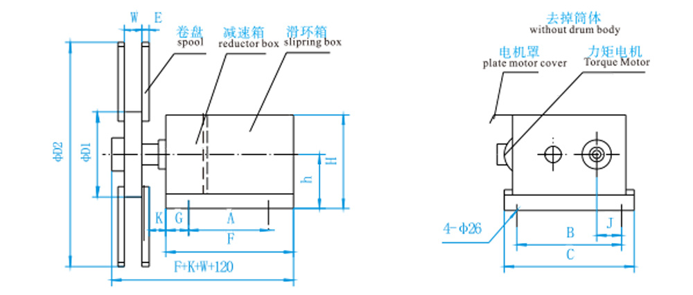
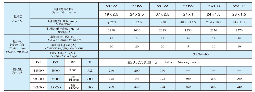
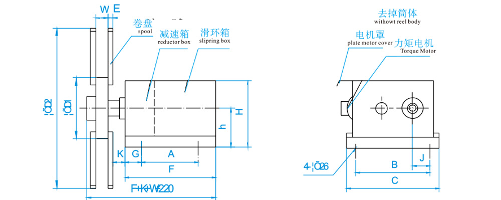
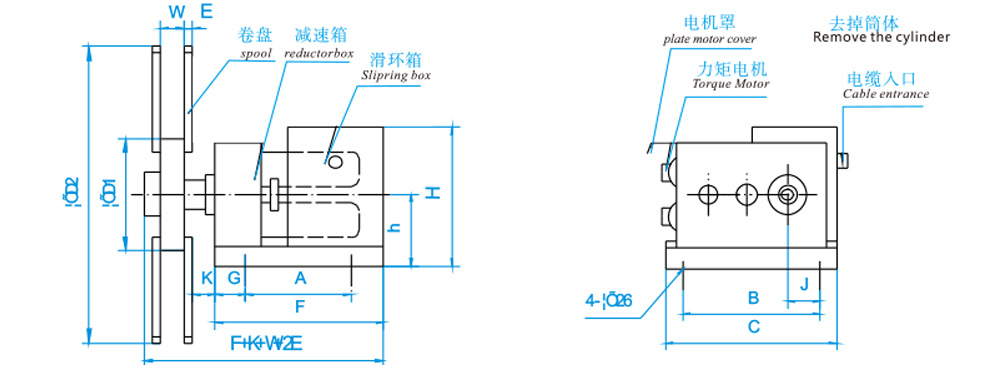
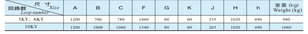
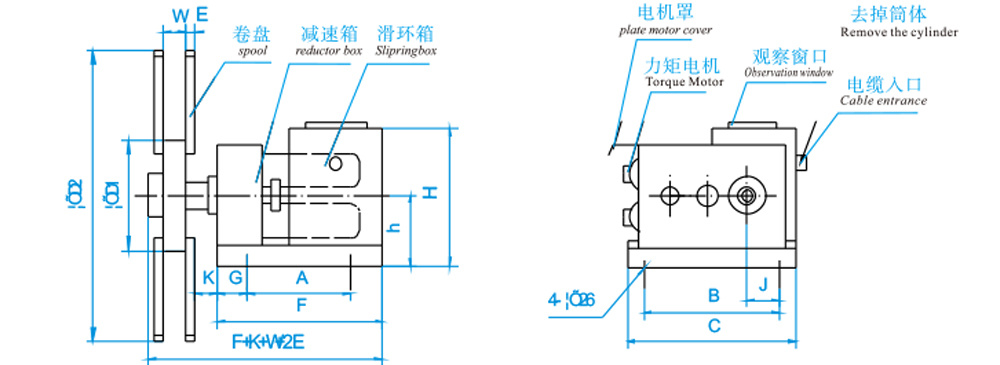
Outline Structure and Installation Dimension Table
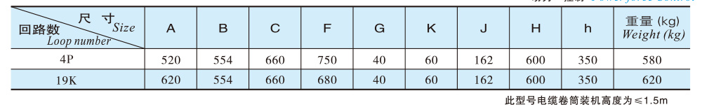
Roller parameters

Outline Dimension Diagram
JM25D-□-4P Outline Structure and Installation Dimension Table

Roller parameters

JM25D-□-19K~37K Outline Structure and Mounting Dimension Table

Roller parameters
Outline Dimension Diagram
JM50D-□-4P Outline Structure and Installation Dimension Table

Roller parameters
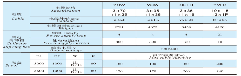
JM100D-□-4P Outline Structure and Installation Dimension Table

Roller parameters
Outline Dimension Diagram
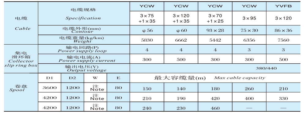
JM120D-□-4P Outline Structure and Installation Dimension Table

Roller parameters
JM100D-□-4P-3kV, 6kV, 10kV — Outline Structure and Installation Dimension Table
Roller parameters
Outline Dimension Diagram
Model Description
Host
1. Power Section
Long-term locked-rotor torque motor (with brake), dedicated gearbox (unit), and collector slip ring box.
Parameters of the long-term locked-rotor torque motor [For reference only]
Electrical Parameters and Characteristics of Long-Term Locked-Rotor Torque Motors
1.1 The tension remains constant as the cable moves from an empty reel to a full reel, making it suitable for applications involving long-term low-speed operation with frequent forward and reverse rotations.
1.2 Unlike conventional motors, this motor has a small locked-rotor current and can withstand prolonged locked-rotor conditions and reverse rotation.
1.3. Before assembly, a locked-rotor test lasting 8–10 hours was conducted. The motor temperature rise was less than 65 K, and under hot conditions, the reduction in locked-rotor torque remained within a range of 5%.
Torque Motor Brake Diagram
The brake consists of a magnetic yoke, an excitation coil, a spring, a brake disc, an armature, a gear sleeve, a manual release mechanism, screws, and other components.
The brake is mounted on the rear end cover of the motor. Adjust the mounting screws to achieve the appropriate air (or gap) clearance. The motor’s transmission shaft is connected to the brake disc via a gear sleeve.
When the excitation coil of the brake is connected to its rated voltage (DC), the electromagnetic force pulls the armature, causing it to disengage from the brake disc (releasing the brake). At this point, the motor shaft drives the brake disc to rotate normally. When the motor is de-energized, the brake is also simultaneously de-energized. At this moment, the spring presses against the armature, forcing the brake disc to generate a frictional torque against both the armature and the flange plate, thereby bringing the motor shaft to a rapid stop.
2. Power (Signal) Transmission Section
Collector slip ring boxes can be classified according to their purpose into power transmission and signal transmission; and according to voltage levels, they include 220V, 500V, 3kV, 6kV, 10kV, and others.
II. Cable Accommodation Section
Reel: Reels can be categorized into multi-row winding and single-row winding. For ease of transportation, reels with diameters ≤3m have an integral structure; reels larger than 3m are assembled components that are put together on-site.
Assembly Diagram of the Reel
III. Cable Guide Bracket Installation Diagram
4. Electrical schematic diagram of the cable reel
Long-term locked-rotor torque motor-type cable reel
Working principle
In cable reels driven by long-term locked-rotor torque motors, both the power transmission and speed-control components are handled by the motor itself. This type of motor possesses unique electrical and mechanical characteristics. It features a wide speed-regulation range and relatively soft mechanical characteristics: when the load changes, the motor’s operating speed adjusts accordingly—increasing load leads to a decrease in speed, while decreasing load results in an increase in speed. Moreover, the motor can operate stably and continuously at any point along its torque-speed characteristic curve, thereby ensuring that the cable maintains an appropriate winding speed and tensile force at the corresponding radius on the reel.
1. Cable winding: The motor’s output torque serves as the driving force, which, through a reduction gear, drives the reel to wind up the cable.
2. Cable Release: The motor’s output torque acts as a resisting force, preventing the cable from rapidly unwinding from the reel and ensuring synchronized cable release.
3. During shutdown: The motor, which is designed for prolonged locked-rotor operation and equipped with a disc-type normally-closed brake, ensures that the cable will not slide off the reel under the influence of gravity when the power is cut off.
Selection Considerations
1. The height of the cable reel handling machine in this series is ≤3m. If the installation height exceeds 3m, please contact our company for assistance in selecting the appropriate model.
2. When placing an order, you must specify parameters such as cable specifications, cable reel length, installation height, and trolley running speed.
3. When winding in a single row, the width W of the reel shall be determined as follows: W = 1.1 times the diameter of the round cable, or W = 1.2 times the width of the flat cable.
Outline Structure and Installation Dimension Table
Roller parameters
Outline Dimension Diagram
JM25D-□-4P Outline Structure and Installation Dimension Table
Roller parameters
JM25D-□-19K~37K Outline Structure and Mounting Dimension Table
Roller parameters
Outline Dimension Diagram
JM50D-□-4P Outline Structure and Installation Dimension Table
Roller parameters
JM100D-□-4P Outline Structure and Installation Dimension Table
Roller parameters
Outline Dimension Diagram
JM120D-□-4P Outline Structure and Installation Dimension Table
Roller parameters
JM100D-□-4P-3kV, 6kV, 10kV — Outline Structure and Installation Dimension Table
Roller parameters
Outline Dimension Diagram
Key words:
Electromagnetic equipment manufacturing, multi-function lifting electromagnet, special lifting electromagnet, multi-purpose lifting electromagnet, permanent magnet coupling hysteresis head
Previous Page
Next Page
RELATED PRODUCTS

This series is designed for lifting and handling cast iron ingots, steel balls, pig iron blocks, machined chips; return materials, iron concentrate powder, cut-off ends; packaged scrap steel, and more. The excitation methods available include: rated voltage DC 220V mode; and strong excitation mode—over-excitation mode.
This series features oval-shaped lifting electromagnets, primarily used for efficiently loading and unloading scrap steel in narrow vehicle compartments. Customization is available based on the specific dimensions of the vehicle compartment.
This series features the most widely used rectangular electromagnets, primarily suited for lifting billets, ingots, and large initial rolling billets. They can also be used for lifting round billets and structural steel. Different magnetic circuit designs are employed to accommodate various types of steel.
Online consultation

The company will continue to develop and innovate with the enterprise spirit of worrying about customers first and enjoying the happiness of customers later, and strive to become a giant of modern enterprises. Welcome all friends to visit and guide our company!
Address: Liji Avenue, Junshan Industrial Park, Yueyang City, Hunan Province
Fax: 0730-8647119