


Products
-
-
Raw billets, beam billets, and plate billets are lifted using electric lifting magnets.
-
Specialized Lifting Electromagnet for High-Speed Wire (Coil)
-
Pipe blanks, steel pipes, large round blanks for lifting with electric lifting magnets
-
Heavy rail, steel pipe lifting with electric lifting magnets
-
Medium-thick steel plate lifting with electric lifting magnet
-
Medium-thick steel plate multi-sheet lifting special lifting electromagnet
RELATED INFORMATION
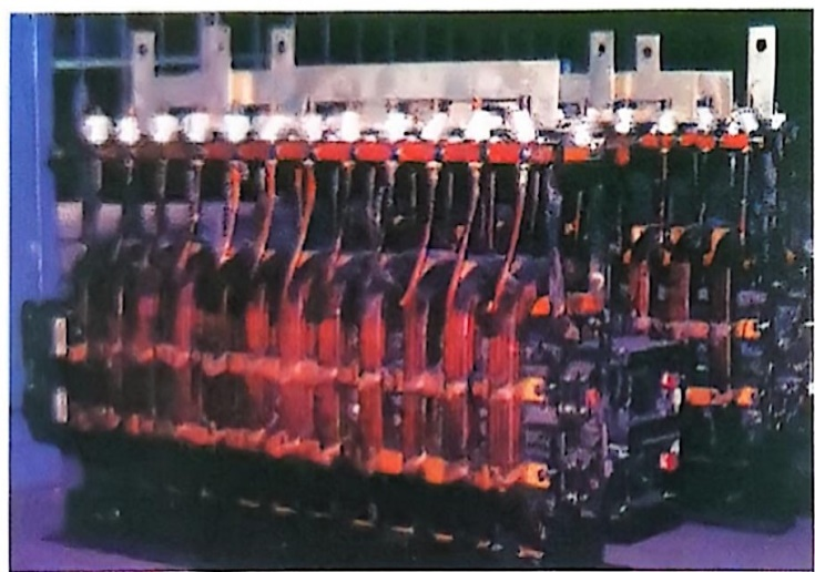
Six-Flow EMS Electromagnetic Stirring YSVF3-J-380 Control System Cabinet
Electromagnetic stirring (EMS for short) is a new technology that leverages the electromagnetic forces induced in the liquid zone of the casting billet to intensify the movement of molten steel, thereby improving the flow, heat transfer, and uniform distribution of alloy elements during solidification and enhancing the internal quality of the casting billet. This technology plays a crucial role in improving steel quality, enabling high-speed continuous casting, expanding the range of steel grades amenable to continuous casting, and relaxing the process conditions required for continuous casting.
Classification:
E-mail:hnyysg0730@163.com
Case Details
Electromagnetic stirring complete set of equipment
I. Basic Principles
Electromagnetic stirring (EMS for short) is a new technology that leverages the electromagnetic forces induced in the liquid phase zone of continuous casting billets to intensify the movement of molten steel, thereby improving the flow, heat transfer, and uniform distribution of alloy elements during solidification and enhancing the internal quality of the billet. This technology plays a crucial role in improving steel quality, enabling high-speed continuous casting, expanding the range of steel grades that can be continuously cast, and relaxing the process conditions for continuous casting.
The operating principle of electromagnetic stirring is similar to that of a solid-rotor induction motor. Specifically, the alternating magnetic field generated by the stirrer penetrates into the liquid zone of the casting billet and induces currents within it. These induced currents interact with the magnetic field generated by the stirrer, producing electromagnetic forces that drive the movement of the molten steel. The electromagnetic stirrer functions like the stator of a solid-rotor induction motor, while the molten steel acts as the rotor of the motor.
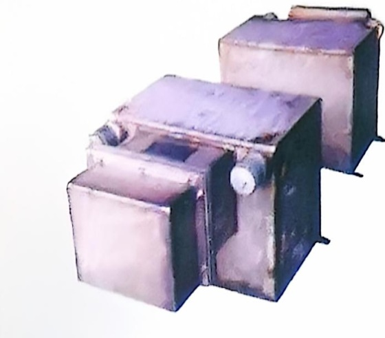
2. Composition of the Electromagnetic Stirring Complete Set of Equipment
The complete set of electromagnetic stirring equipment consists of an electromagnetic stirrer, a variable-frequency power supply, control equipment, and a cooling water treatment system.
3. Combination Methods for Electromagnetic Stirring Complete Sets of Equipment
. IV. Metallurgical Effects
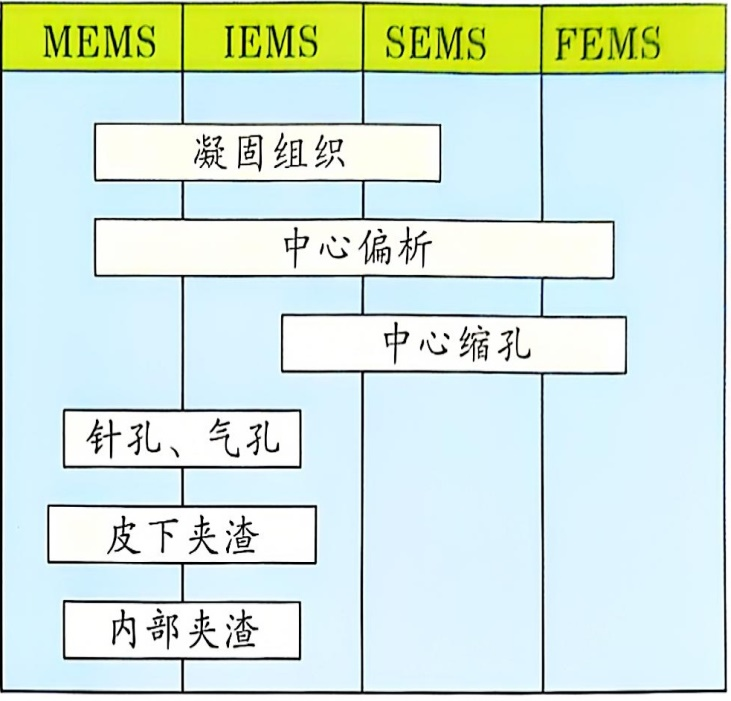
·Electromagnetic stirring can refine the internal microstructure of billets, improve the surface quality of cast billets, promote the flotation of non-metallic inclusions in the molten steel, reduce central segregation and central porosity, and increase the proportion of equiaxed crystals.
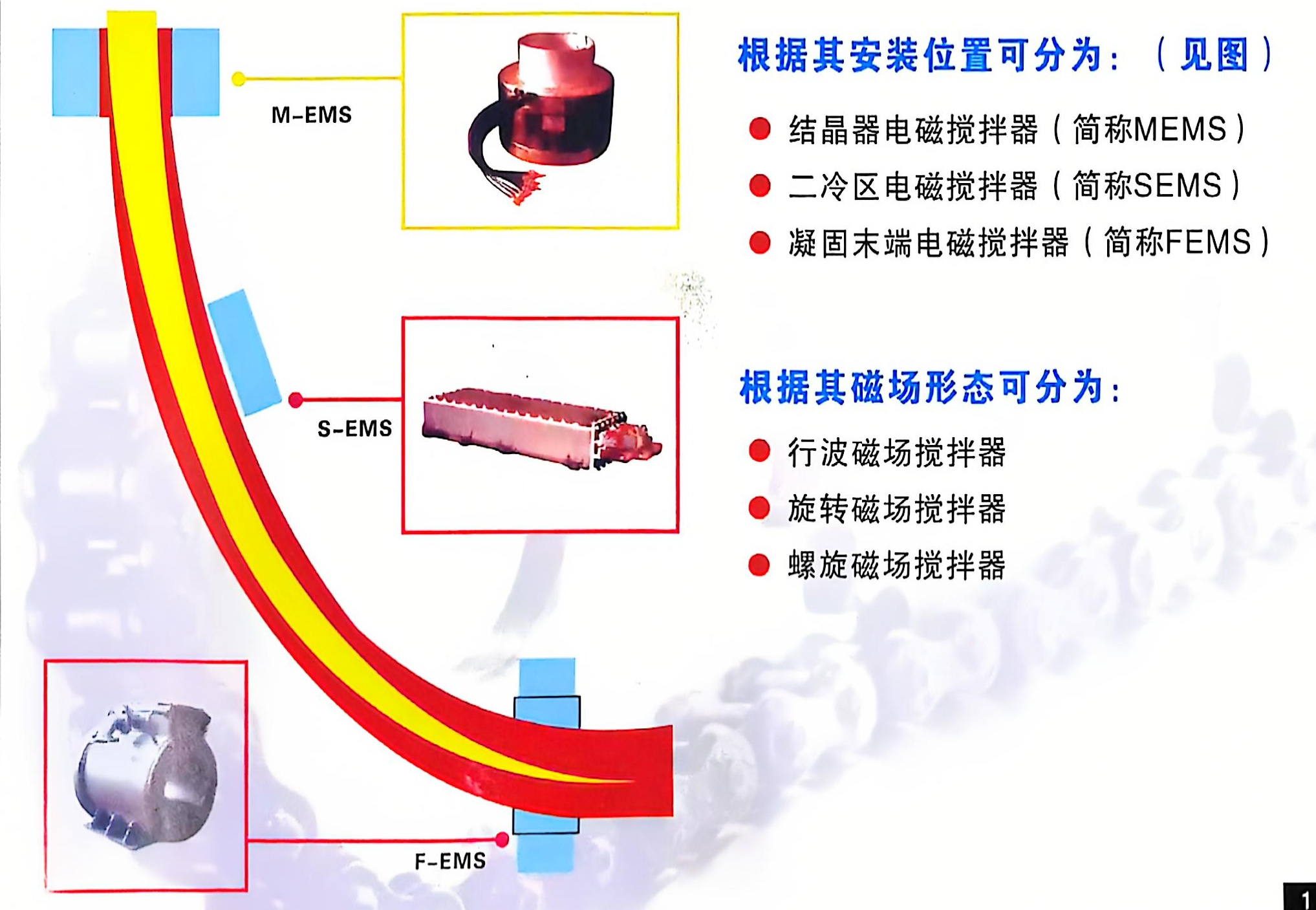
·Different installation positions of electromagnetic stirrers yield different metallurgical effects. The primary metallurgical effects of these stirrers in improving the quality of cast billets are shown in the table.
5. Classification of electromagnetic stirrers
- Mold electromagnetic stirring
Electromagnetic stirrers for crystallizers are classified into built-in and external types according to their relative positions with respect to the crystallizer.
- Built-in electromagnetic stirrer
The built-in electromagnetic stirrer is installed inside the crystallizer’s water tank. Its features include: the induction coil is closely positioned adjacent to the copper sleeve and water jacket of the casting billet, providing excellent stirring performance; it requires low electrical power and has low operating costs; the crystallizer is cooled by water, eliminating the need for a separate cooling water system; each crystallizer needs to be equipped with a stirring coil, resulting in a large number of spare parts required.
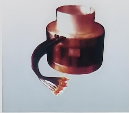
Built-in crystallization-section electromagnetic stirrer
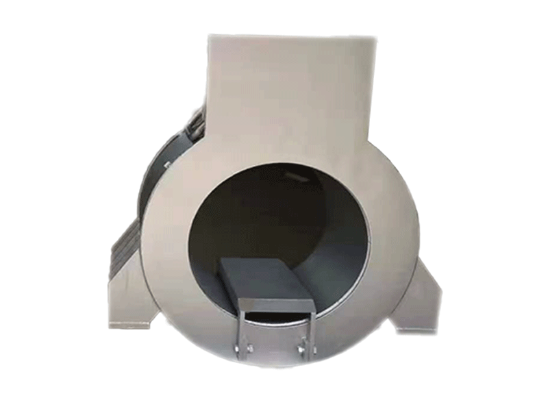
- External electromagnetic stirrer
The external electromagnetic stirrer is installed around the outside of the crystallizer.
(1) Direct Water-Immersion Cooling Type Characteristics: Convenient for replacing the crystallizer; relatively high energy consumption and operating costs; requires few spare parts; uses crystallization water for cooling, eliminating the need for a separate cooling water system.
(2) Characteristics of the internal-cooling type hollow copper tube: Convenient for replacing the crystallizer; high cooling efficiency due to internal cooling in the hollow copper tube; requires fewer spare parts; relatively high energy consumption and operating costs; necessitates a separate cooling water treatment system.
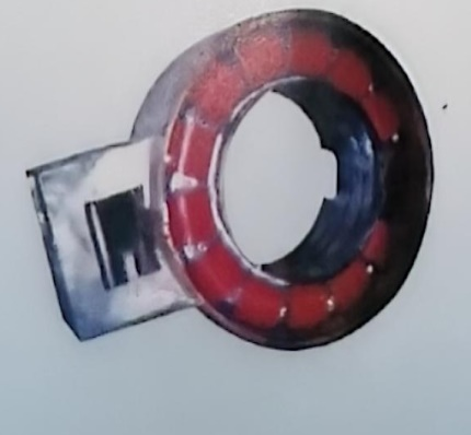
External Crystallization Section Electromagnetic Stirrer
Electromagnetic Stirrer for Secondary Cooling Zone
The electromagnetic stirrer (SEMS) is installed in the secondary cooling zone of continuous casting machines. For billets, the electromagnetic stirring in the secondary cooling zone typically employs a unidirectional traveling-wave magnetic field configuration, which is mounted on the inner arc side of the cast slab. Alternatively, a rotating magnetic field configuration may also be used. For slabs, the electromagnetic stirring in the secondary cooling zone usually adopts a bidirectional traveling-wave magnetic field configuration.
Field linear mixer
Secondary Cooling Zone Slab Electromagnetic Stirrer
Electromagnetic Stirrer for the Solidification End
Electromagnetic stirrers installed at the solidification end of continuous casting machines all employ rotating magnetic field types. Depending on the cross-section of the cast billet, either low-frequency or power-frequency excitation can be used.
Electromagnetic Stirrer for the Solidification End
Combination methods of electromagnetic stirrers
Based on the configuration of the magnetic electromagnetic stirrer used in the Genzhezhou River, its combination method is...
| Combination method |
Applicable steel grades |
Billet type |
Note |
| M+F---EMS |
Medium- and high-carbon steels (including alloy steels and bearing steels) |
Billet |
The currently widely used method |
| M+S---EMS |
Medium- and high-carbon steels (including alloy steels and spring steels) |
Billet |
|
| S+F---EMS |
Medium- and carbon steel |
Large-section billet |
|
| M+S+F---EMS |
Ultra-high carbon steel |
Small billet |
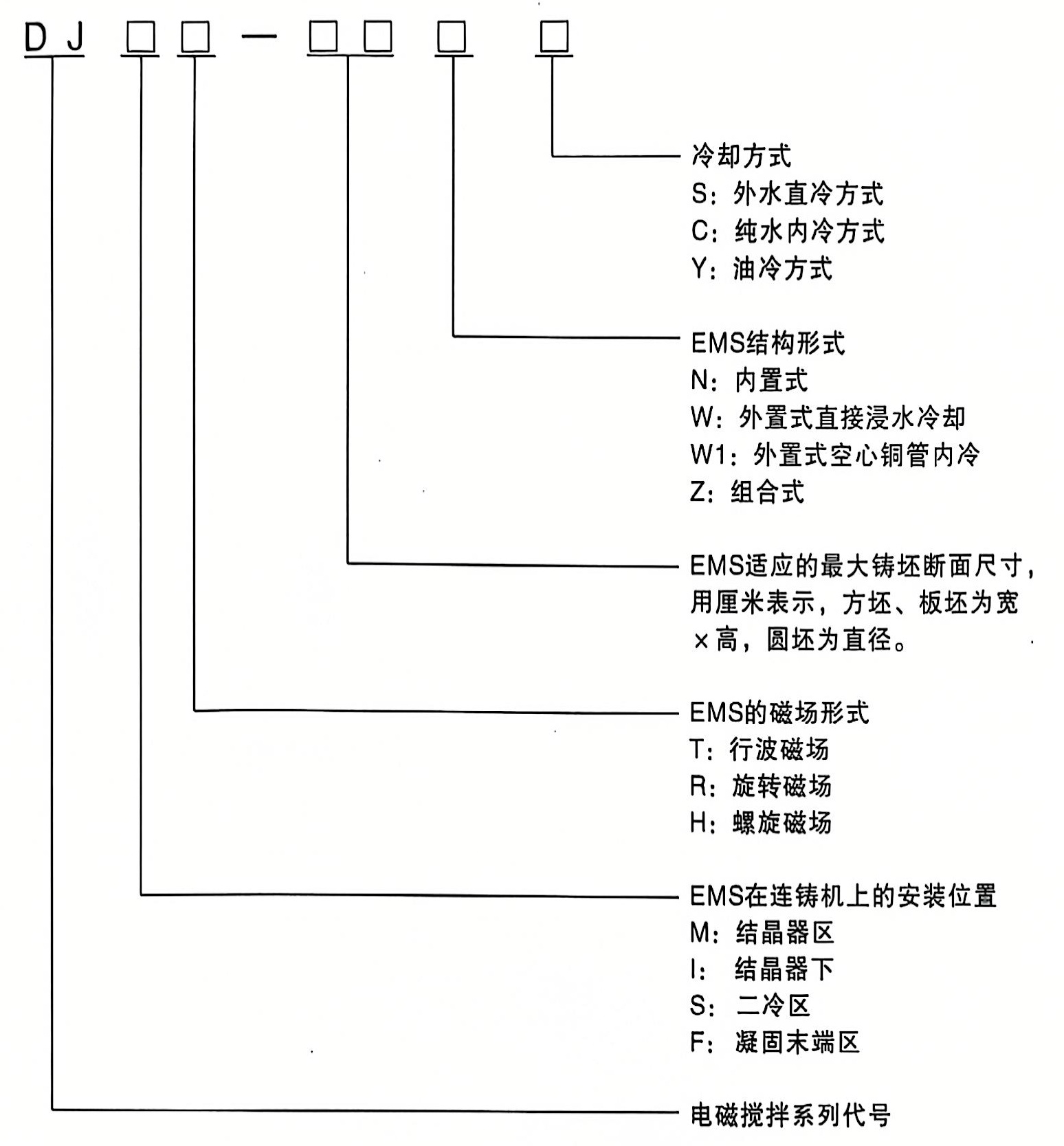
Model Description
Model and Meaning of Electromagnetic Stirrers (EMS)
 Parameters required when placing an order
The selection of an electromagnetic stirrer is generally determined by the following conditions:
△ Continuous Casting Machine Model
△Continuous Casting Steel Grades
△ Continuous casting billet cross-section
△ Installation Area
△ Built-in type must provide the crystallizer tank dimensions.
△ The external type provides the crystallizer dimensions and flow spacing.
△Water jacket dimensions
△ Copper pipe dimensions and thickness
Electromagnetic Stirring Control System
Currently, the electromagnetic stirring control systems produced by our company are mainly used in two major categories: one is the three-phase electromagnetic stirring control system for continuous casting of round and square billets and slabs, and the other is the two-phase orthogonal electromagnetic stirring control system for tundishes.
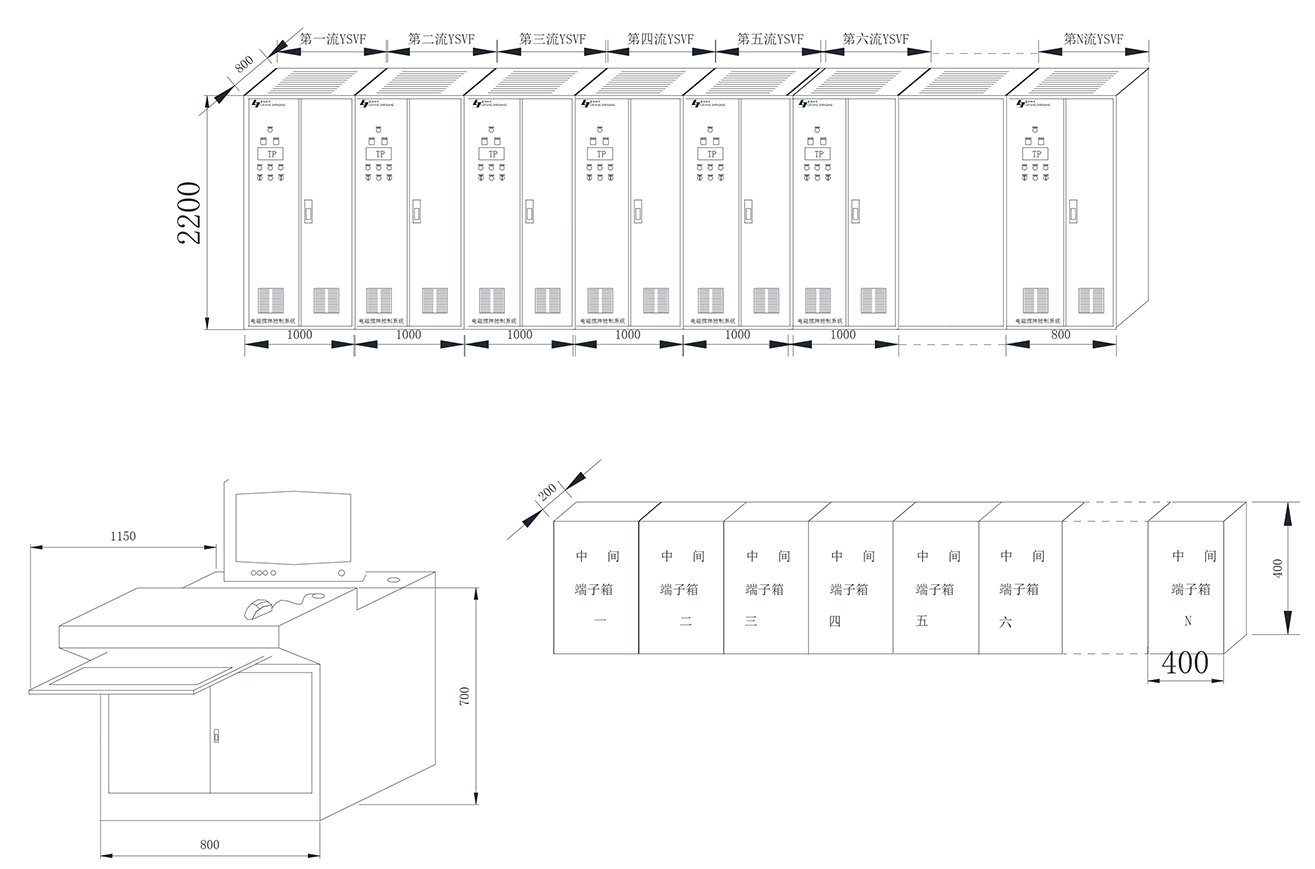
I. Three-phase Electromagnetic Stirring (EMS) Control System for Continuous Casting of Billets and Slabs
The general N-stream M-section electromagnetic stirring control system for continuous casting consists of a monitoring system, a process control system, and NxM sets of three-phase low-frequency current systems (YSVF3), among other components. The low-frequency power supply outputs a three-phase low-frequency sinusoidal current.
II. Two-phase orthogonal electromagnetic stirring control system for tundishes
The tundish electromagnetic stirring control system mainly consists of a monitoring system, a process control system, and a two-phase low-frequency power supply system (YSVF2). The output of its low-frequency power supply is a pair of orthogonal, low-frequency sinusoidal currents.
III. Block Diagram and External View of the Electromagnetic Stirring Control System
IV. Main Features of the System
1. It adopts the latest advancements in power electronics technology and microcomputer control technology currently available internationally, featuring advanced technology, excellent performance, simple operation, convenient maintenance, and a long service life.
2. Equipped with two operation sites: remote and on-site.
3. Equipped with manual and automatic operation functions.
4. Three operating modes—continuous, intermittent, and alternating—can be adopted.
5. Equipped with control functions for three magnetic field patterns: rotating, traveling wave, and helical.
6. The current and frequency of each low-frequency power supply system are independently adjustable without interfering with each other, and the control method is current closed-loop control.
7. The system features sophisticated electromagnetic compatibility design and protective function design, giving it strong anti-interference capability and ensuring stable and reliable operation.
8. Possesses excellent network communication capabilities and is highly flexible.
9. The monitoring system offers two types: a standard operating system with an industrial control interface, and a standard operator panel type. The standard operator panel type is slightly less expensive than the full industrial control interface type; users can select based on their specific needs.
10. Since the main frequency conversion circuit in the low-frequency power supply device adopts an AC-DC-AC voltage-source frequency conversion and voltage regulation approach, the frequency and voltage modulation is implemented using DSP or a single-chip microcomputer to achieve high-carrier SPWM modulation. The inverter section employs fully controlled IGBT power modules or IPM intelligent power modules, configured in either three-phase or two-phase full-bridge topologies. This design results in a compact device with a high carrier frequency, excellent output waveform quality, and a high power factor. The device can deliver a maximum output current of 1200 A, with an adjustable output frequency ranging from 2 to 30 Hz, and a maximum output voltage of 460 V.
11. The three-phase low-frequency power supply system comes in two types: a fully domestically produced model and a variable-voltage, variable-frequency (VVVF) model that partially adopts an imported electromagnetic stirring-specific frequency converter module. The fully domestically produced model is preferable to the VVVF model that uses an imported electromagnetic stirring-specific variable-voltage, variable-frequency module; users can select the appropriate model based on their specific requirements.
V. Model Description of the Electromagnetic Stirring Control System

Note: The rated output capacity refers to the output capacity of a single low-frequency power supply system.
VI. Selection Instructions
The selection of an electromagnetic stirring control system is generally determined by the following factors:
1. Current, voltage, frequency, capacity, and number of phases of the electromagnetic stirring coil.
2. The number of strands in the continuous casting machine or the number of tundishes.
3. The number of physical quantity parameters that need to be measured and monitored in the water system.
4. The number of physical parameter quantities that require interlocks at the user’s site.
5. Other specific requirements from the user.
Technical Parameters of Continuous Casting Electromagnetic Stirring Complete Set of Equipment
| Model |
Installation location |
Magnetic field form |
Maximum Stirring Cross-Section (mm²) |
Capacity (KVA) |
Current (A) |
Frequency (HZ) |
Maximum external dimensions (mm²) |
Self-weight (KG) |
Power supply equipment配套 |
Cooling method |
|
DJZR-10T |
Tundish exterior |
Rotating magnetic field |
10T centrifuge Tundish |
540 |
750 |
2-10 Two-phase orthogonal |
Φ1627x1170 |
3200 |
YSVF2-J-600 |
|
|
DJMR-2S32NS |
-
Conclusion
Crystal
device
Inside |
Rotating magnetic field |
280x320 |
260 |
500 |
2-10 |
Φ820x420 |
540 |
YSVF3-J-300
|
Direct water cooling from external sources |
|
DJMR-2625NS |
Rotating magnetic field |
250x250 |
220 |
400 |
3-12 |
Φ700x420 |
400 |
YSVF3-J-260
|
||
|
DJMR-2222NS |
Rotating magnetic field |
220x220 |
180 |
400 |
3-12 |
Φ660x400 |
360 |
YSVF3-J-220
|
||
|
DJMR-2020NS |
Rotating magnetic field |
200x200 |
150 |
400 |
3-12 |
Φ660x400 |
360 |
YSVF3-J-200
|
||
| DJMR-1616NS |
Rotating magnetic field |
160x160 |
130 |
350 |
3-12 |
Φ670x476 |
320 |
YSVF3-J-200
|
||
| DJMR-1515NS |
Rotating magnetic field |
150x150 |
140 |
300 |
3-11 |
Φ580x500 |
300 |
YSVF3-J-180
|
||
| DJMR-2838WC |
Conclusion
Crystal
device Outside |
Rotating magnetic field |
280x380 |
350 |
550 |
2-9 |
Φ1240x500 |
1600 |
YSVF3-J-420
|
Pure water internal cooling |
| DJMR-2528WC |
Rotating magnetic field |
250x280 |
260 |
360 |
2-9 |
Φ1120x470 |
110 |
YSVF3-J-280
|
||
| DJMR-2222WC |
Rotating magnetic field |
220x220 |
240 |
360 |
2-10 |
Φ900x480 |
850 |
YSVF3-J-280
|
||
| DJMR-2020WS |
Rotating magnetic field |
200x200 |
200 |
360 |
2-12 |
Φ830x350 |
680 |
YSVF3-J-220
|
||
| DJMR-2838WS |
Rotating magnetic field |
280x380 |
400 |
600 |
2-9 |
Φ1270x680 |
1800 |
YSVF3-J-490
|
Direct water cooling from external sources |
|
| DJMR-2424WS |
Rotating magnetic field |
|
320 |
500 |
2-10 |
Φ920x450 |
850 |
YSVF3-J-350
|
||
| DJMR-1822WS |
Rotating magnetic field |
180x220 |
300 |
500 |
2-10 |
Φ880x480 |
980 |
YSVF3-J-350
|
||
| DJMR-1515WS |
Rotating magnetic field |
150x150 |
280 |
500 |
3-12 |
Φ830x530 |
880 |
YSVF3-J-300
|
||
| DJST-19030ZC |
Two Cold district |
Traveling wave magnetic field |
1900x300 |
250
|
|
4-12 |
1610x1610x500 |
1500x2 |
YSVF3-J-800
|
Pure water internal cooling |
| DJST-2828ZS |
Traveling wave magnetic field |
280x280 |
430 |
1000 |
50 |
1160x624x563 |
630 |
YSVF2-J-500 |
Direct water cooling from external sources |
|
| DJST-2020ZY |
Traveling wave magnetic field |
200x200 |
130 |
180 |
50 |
760x600x340 |
450 |
YSVF2-J-200 |
Oil-water secondary cooling |
|
| DJFR-2528WC |
Rotating magnetic field |
250x280 |
350 |
600 |
6-15 |
Φ820x550 |
930 |
YSVF3-J-420
|
Pure water Internal cooling |
|
| DJFR-2222WC |
Rotating magnetic field |
220x220 |
300 |
500 |
6-15 |
Φ730x550 |
720 |
YSVF3-J-350
|
||
| DJFR-2020WC |
Rotating magnetic field |
200x200 |
300 |
500 |
6-15 |
Φ780x520 |
YSVF3-J-350 |
|||
Technical Parameters of Continuous Casting Electromagnetic Stirring Device
| Model |
Installation location |
Magnetic field form |
Maximum Stirring Cross-Section (mm²) |
Capacity (KVA) |
Current (A) |
Frequency (HZ) |
Maximum external dimensions (mm²) |
Self-weight (KG) |
Power supply equipment配套 |
Cooling method |
|
DJZR-10T |
Tundish exterior |
Rotating magnetic field |
10T centrifuge Tundish |
540 |
750 |
2-10 Two-phase orthogonal |
Φ1627x1170 |
3200 |
YSVF2-J-600 |
|
|
DJMR-2S32NS |
-
Conclusion
Crystal
device
Inside |
Rotating magnetic field |
280x320 |
260 |
500 |
2-10 |
Φ820x420 |
540 |
YSVF3-J-300 |
Direct water cooling from external sources |
| YSVF3-J1-300 |
||||||||||
|
DJMR-2625NS |
Rotating magnetic field |
250x250 |
220 |
400 |
3-12 |
Φ700x420 |
400 |
YSVF3-J-260 |
||
| YSVF3-J1-260 |
||||||||||
|
DJMR-2222NS |
Rotating magnetic field |
220x220 |
180 |
400 |
3-12 |
Φ660x400 |
360 |
YSVF3-J-220 |
||
| YSVF3-J1-220 |
||||||||||
|
DJMR-2020NS |
Rotating magnetic field |
200x200 |
150 |
400 |
3-12 |
Φ660x400 |
360 |
YSVF3-J-200 |
||
| YSVF3-J1-200 |
||||||||||
| DJMR-1616NS |
Rotating magnetic field |
160x160 |
130 |
350 |
3-12 |
Φ670x476 |
320 |
YSVF3-J-200 |
||
| YSVF3-J1-200 |
||||||||||
| DJMR-1515NS |
Rotating magnetic field |
150x150 |
140 |
300 |
3-11 |
Φ580x500 |
300 |
YSVF3-J-180 |
||
| YSVF3-J1-180 |
||||||||||
| DJMR-2838WC |
Conclusion
Crystal
device Outside |
Rotating magnetic field |
280x380 |
350 |
550 |
2-9 |
Φ1240x500 |
1600 |
YSVF3-J-420 |
Pure water internal cooling |
| YSVF3-J1-420 |
||||||||||
| DJMR-2528WC |
Rotating magnetic field |
250x280 |
260 |
360 |
2-9 |
Φ1120x470 |
110 |
YSVF3-J-280 |
||
| YSVF3-J1-280 |
||||||||||
| DJMR-2222WC |
Rotating magnetic field |
220x220 |
240 |
360 |
2-10 |
Φ900x480 |
850 |
YSVF3-J-280 |
||
| YSVF3-J1-280 |
||||||||||
| DJMR-2020WS |
Rotating magnetic field |
200x200 |
200 |
360 |
2-12 |
Φ830x350 |
680 |
YSVF3-J-220 |
||
| YSVF3-J1-220 |
||||||||||
| DJMR-2838WS |
Rotating magnetic field |
280x380 |
400 |
600 |
2-9 |
Φ1270x680 |
1800 |
YSVF3-J-490 |
Direct water cooling from external sources |
|
| YSVF3-J1-420 |
||||||||||
| DJMR-2424WS |
Rotating magnetic field |
|
320 |
500 |
2-10 |
Φ920x450 |
850 |
YSVF3-J-350 |
||
| YSVF3-J-350 |
||||||||||
| DJMR-1822WS |
Rotating magnetic field |
180x220 |
300 |
500 |
2-10 |
Φ880x480 |
980 |
YSVF3-J-350 |
||
| YSVF3-J1-350 |
||||||||||
| DJMR-1515WS |
Rotating magnetic field |
150x150 |
280 |
500 |
3-12 |
Φ830x530 |
880 |
YSVF3-J-300 |
||
| YSVF3-J1-300 |
||||||||||
| DJST-19030ZC |
Two
Cold zone |
Traveling wave magnetic field |
1900x300 |
|
|
4-12 |
1610x1610x500 |
1500x2 |
YSVF3-J-800 |
Pure water internal cooling |
| YSVF3-J1-800 |
||||||||||
| DJST-17025ZC |
Traveling wave magnetic field |
|
|
|
6-20 |
1610x600x500 |
1300x2 |
YSVF3-J-800 |
||
| YSVF3-J1-800 |
||||||||||
| DJST-2828ZS |
Traveling wave magnetic field |
280x280 |
430 |
1000 |
50 |
1160x624x563 |
630 |
YSGK-J-500 |
Direct water cooling from external sources |
|
| DJST-2020ZY |
Traveling wave magnetic field |
200x200 |
130 |
180 |
50 |
760x600x340 |
450 |
YSGK-J-200 |
Oil-water secondary cooling |
|
| DJFR-2528WC |
Rotating magnetic field |
250x280 |
350 |
600 |
6-15 |
Φ820x550 |
930 |
YSVF3-J-420 |
Pure water Internal cooling |
|
| YSVF3-J1-420 |
||||||||||
| DJFR-2222WC |
Rotating magnetic field |
220x220 |
300 |
500 |
6-15 |
Φ730x550 |
720 |
YSVF3-J-350 |
||
| YSVF3-J1-350 |
||||||||||
| DJFR-2020WC |
Rotating magnetic field |
200x200 |
300 |
500 |
6-15 |
Φ780x520 |
678 |
YSVF3-J-350 |
||
| YSVF3-J1-350 |
Electromagnetic stirring complete set of equipment
I. Basic Principles
Electromagnetic stirring (EMS for short) is a new technology that leverages the electromagnetic forces induced in the liquid phase zone of continuous casting billets to intensify the movement of molten steel, thereby improving the flow, heat transfer, and uniform distribution of alloy elements during solidification and enhancing the internal quality of the billet. This technology plays a crucial role in improving steel quality, enabling high-speed continuous casting, expanding the range of steel grades that can be continuously cast, and relaxing the process conditions for continuous casting.
The operating principle of electromagnetic stirring is similar to that of a solid-rotor induction motor. Specifically, the alternating magnetic field generated by the stirrer penetrates into the liquid zone of the casting billet and induces currents within it. These induced currents interact with the magnetic field generated by the stirrer, producing electromagnetic forces that drive the movement of the molten steel. The electromagnetic stirrer functions like the stator of a solid-rotor induction motor, while the molten steel acts as the rotor of the motor.
2. Composition of the Electromagnetic Stirring Complete Set of Equipment
The complete set of electromagnetic stirring equipment consists of an electromagnetic stirrer, a variable-frequency power supply, control equipment, and a cooling water treatment system.
3. Combination Methods for Electromagnetic Stirring Complete Sets of Equipment
. IV. Metallurgical Effects
·Electromagnetic stirring can refine the internal microstructure of billets, improve the surface quality of cast billets, promote the flotation of non-metallic inclusions in the molten steel, reduce central segregation and central porosity, and increase the proportion of equiaxed crystals.
·Different installation positions of electromagnetic stirrers yield different metallurgical effects. The primary metallurgical effects of these stirrers in improving the quality of cast billets are shown in the table.
5. Classification of electromagnetic stirrers
- Mold electromagnetic stirring
Electromagnetic stirrers for crystallizers are classified into built-in and external types according to their relative positions with respect to the crystallizer.
- Built-in electromagnetic stirrer
The built-in electromagnetic stirrer is installed inside the crystallizer’s water tank. Its features include: the induction coil is closely positioned adjacent to the copper sleeve and water jacket of the casting billet, providing excellent stirring performance; it requires low electrical power and has low operating costs; the crystallizer is cooled by water, eliminating the need for a separate cooling water system; each crystallizer needs to be equipped with a stirring coil, resulting in a large number of spare parts required.
Built-in crystallization-section electromagnetic stirrer
- External electromagnetic stirrer
The external electromagnetic stirrer is installed around the outside of the crystallizer.
(1) Direct Water-Immersion Cooling Type Characteristics: Convenient for replacing the crystallizer; relatively high energy consumption and operating costs; requires few spare parts; uses crystallization water for cooling, eliminating the need for a separate cooling water system.
(2) Characteristics of the internal-cooling type hollow copper tube: Convenient for replacing the crystallizer; high cooling efficiency due to internal cooling in the hollow copper tube; requires fewer spare parts; relatively high energy consumption and operating costs; necessitates a separate cooling water treatment system.
External Crystallization Section Electromagnetic Stirrer
Electromagnetic Stirrer for Secondary Cooling Zone
The electromagnetic stirrer (SEMS) is installed in the secondary cooling zone of continuous casting machines. For billets, the electromagnetic stirring in the secondary cooling zone typically employs a unidirectional traveling-wave magnetic field configuration, which is mounted on the inner arc side of the cast slab. Alternatively, a rotating magnetic field configuration may also be used. For slabs, the electromagnetic stirring in the secondary cooling zone usually adopts a bidirectional traveling-wave magnetic field configuration.
Field linear mixer
Secondary Cooling Zone Slab Electromagnetic Stirrer
Electromagnetic Stirrer for the Solidification End
Electromagnetic stirrers installed at the solidification end of continuous casting machines all employ rotating magnetic field types. Depending on the cross-section of the cast billet, either low-frequency or power-frequency excitation can be used.
Electromagnetic Stirrer for the Solidification End
Combination methods of electromagnetic stirrers
Based on the configuration of the magnetic electromagnetic stirrer used in the Genzhezhou River, its combination method is...
| Combination method |
Applicable steel grades |
Billet type |
Note |
| M+F---EMS |
Medium- and high-carbon steels (including alloy steels and bearing steels) |
Billet |
The currently widely used method |
| M+S---EMS |
Medium- and high-carbon steels (including alloy steels and spring steels) |
Billet |
|
| S+F---EMS |
Medium- and carbon steel |
Large-section billet |
|
| M+S+F---EMS |
Ultra-high carbon steel |
Small billet |
Model Description
Model and Meaning of Electromagnetic Stirrers (EMS)
Parameters required when placing an order
The selection of an electromagnetic stirrer is generally determined by the following conditions:
△ Continuous Casting Machine Model
△Continuous Casting Steel Grades
△ Continuous casting billet cross-section
△ Installation Area
△ Built-in type must provide the crystallizer tank dimensions.
△ The external type provides the crystallizer dimensions and flow spacing.
△Water jacket dimensions
△ Copper pipe dimensions and thickness
Electromagnetic Stirring Control System
Currently, the electromagnetic stirring control systems produced by our company are mainly used in two major categories: one is the three-phase electromagnetic stirring control system for continuous casting of round and square billets and slabs, and the other is the two-phase orthogonal electromagnetic stirring control system for tundishes.
I. Three-phase Electromagnetic Stirring (EMS) Control System for Continuous Casting of Billets and Slabs
The general N-stream M-section electromagnetic stirring control system for continuous casting consists of a monitoring system, a process control system, and NxM sets of three-phase low-frequency current systems (YSVF3), among other components. The low-frequency power supply outputs a three-phase low-frequency sinusoidal current.
II. Two-phase orthogonal electromagnetic stirring control system for tundishes
The tundish electromagnetic stirring control system mainly consists of a monitoring system, a process control system, and a two-phase low-frequency power supply system (YSVF2). The output of its low-frequency power supply is a pair of orthogonal, low-frequency sinusoidal currents.
III. Block Diagram and External View of the Electromagnetic Stirring Control System
IV. Main Features of the System
1. It adopts the latest advancements in power electronics technology and microcomputer control technology currently available internationally, featuring advanced technology, excellent performance, simple operation, convenient maintenance, and a long service life.
2. Equipped with two operation sites: remote and on-site.
3. Equipped with manual and automatic operation functions.
4. Three operating modes—continuous, intermittent, and alternating—can be adopted.
5. Equipped with control functions for three magnetic field patterns: rotating, traveling wave, and helical.
6. The current and frequency of each low-frequency power supply system are independently adjustable without interfering with each other, and the control method is current closed-loop control.
7. The system features sophisticated electromagnetic compatibility design and protective function design, giving it strong anti-interference capability and ensuring stable and reliable operation.
8. Possesses excellent network communication capabilities and is highly flexible.
9. The monitoring system offers two types: a standard operating system with an industrial control interface, and a standard operator panel type. The standard operator panel type is slightly less expensive than the full industrial control interface type; users can select based on their specific needs.
10. Since the main frequency conversion circuit in the low-frequency power supply device adopts an AC-DC-AC voltage-source frequency conversion and voltage regulation approach, the frequency and voltage modulation is implemented using DSP or a single-chip microcomputer to achieve high-carrier SPWM modulation. The inverter section employs fully controlled IGBT power modules or IPM intelligent power modules, configured in either three-phase or two-phase full-bridge topologies. This design results in a compact device with a high carrier frequency, excellent output waveform quality, and a high power factor. The device can deliver a maximum output current of 1200 A, with an adjustable output frequency ranging from 2 to 30 Hz, and a maximum output voltage of 460 V.
11. The three-phase low-frequency power supply system comes in two types: a fully domestically produced model and a variable-voltage, variable-frequency (VVVF) model that partially adopts an imported electromagnetic stirring-specific frequency converter module. The fully domestically produced model is preferable to the VVVF model that uses an imported electromagnetic stirring-specific variable-voltage, variable-frequency module; users can select the appropriate model based on their specific requirements.
V. Model Description of the Electromagnetic Stirring Control System
Note: The rated output capacity refers to the output capacity of a single low-frequency power supply system.
VI. Selection Instructions
The selection of an electromagnetic stirring control system is generally determined by the following factors:
1. Current, voltage, frequency, capacity, and number of phases of the electromagnetic stirring coil.
2. The number of strands in the continuous casting machine or the number of tundishes.
3. The number of physical quantity parameters that need to be measured and monitored in the water system.
4. The number of physical parameter quantities that require interlocks at the user’s site.
5. Other specific requirements from the user.
Technical Parameters of Continuous Casting Electromagnetic Stirring Complete Set of Equipment
| Model |
Installation location |
Magnetic field form |
Maximum Stirring Cross-Section (mm²) |
Capacity (KVA) |
Current (A) |
Frequency (HZ) |
Maximum external dimensions (mm²) |
Self-weight (KG) |
Power supply equipment配套 |
Cooling method |
|
DJZR-10T |
Tundish exterior |
Rotating magnetic field |
10T centrifuge Tundish |
540 |
750 |
2-10 Two-phase orthogonal |
Φ1627x1170 |
3200 |
YSVF2-J-600 |
|
|
DJMR-2S32NS |
-
Conclusion
Crystal
device
Inside |
Rotating magnetic field |
280x320 |
260 |
500 |
2-10 |
Φ820x420 |
540 |
YSVF3-J-300
|
Direct water cooling from external sources |
|
DJMR-2625NS |
Rotating magnetic field |
250x250 |
220 |
400 |
3-12 |
Φ700x420 |
400 |
YSVF3-J-260
|
||
|
DJMR-2222NS |
Rotating magnetic field |
220x220 |
180 |
400 |
3-12 |
Φ660x400 |
360 |
YSVF3-J-220
|
||
|
DJMR-2020NS |
Rotating magnetic field |
200x200 |
150 |
400 |
3-12 |
Φ660x400 |
360 |
YSVF3-J-200
|
||
| DJMR-1616NS |
Rotating magnetic field |
160x160 |
130 |
350 |
3-12 |
Φ670x476 |
320 |
YSVF3-J-200
|
||
| DJMR-1515NS |
Rotating magnetic field |
150x150 |
140 |
300 |
3-11 |
Φ580x500 |
300 |
YSVF3-J-180
|
||
| DJMR-2838WC |
Conclusion
Crystal
device Outside |
Rotating magnetic field |
280x380 |
350 |
550 |
2-9 |
Φ1240x500 |
1600 |
YSVF3-J-420
|
Pure water internal cooling |
| DJMR-2528WC |
Rotating magnetic field |
250x280 |
260 |
360 |
2-9 |
Φ1120x470 |
110 |
YSVF3-J-280
|
||
| DJMR-2222WC |
Rotating magnetic field |
220x220 |
240 |
360 |
2-10 |
Φ900x480 |
850 |
YSVF3-J-280
|
||
| DJMR-2020WS |
Rotating magnetic field |
200x200 |
200 |
360 |
2-12 |
Φ830x350 |
680 |
YSVF3-J-220
|
||
| DJMR-2838WS |
Rotating magnetic field |
280x380 |
400 |
600 |
2-9 |
Φ1270x680 |
1800 |
YSVF3-J-490
|
Direct water cooling from external sources |
|
| DJMR-2424WS |
Rotating magnetic field |
|
320 |
500 |
2-10 |
Φ920x450 |
850 |
YSVF3-J-350
|
||
| DJMR-1822WS |
Rotating magnetic field |
180x220 |
300 |
500 |
2-10 |
Φ880x480 |
980 |
YSVF3-J-350
|
||
| DJMR-1515WS |
Rotating magnetic field |
150x150 |
280 |
500 |
3-12 |
Φ830x530 |
880 |
YSVF3-J-300
|
||
| DJST-19030ZC |
Two Cold district |
Traveling wave magnetic field |
1900x300 |
250
|
|
4-12 |
1610x1610x500 |
1500x2 |
YSVF3-J-800
|
Pure water internal cooling |
| DJST-2828ZS |
Traveling wave magnetic field |
280x280 |
430 |
1000 |
50 |
1160x624x563 |
630 |
YSVF2-J-500 |
Direct water cooling from external sources |
|
| DJST-2020ZY |
Traveling wave magnetic field |
200x200 |
130 |
180 |
50 |
760x600x340 |
450 |
YSVF2-J-200 |
Oil-water secondary cooling |
|
| DJFR-2528WC |
Rotating magnetic field |
250x280 |
350 |
600 |
6-15 |
Φ820x550 |
930 |
YSVF3-J-420
|
Pure water Internal cooling |
|
| DJFR-2222WC |
Rotating magnetic field |
220x220 |
300 |
500 |
6-15 |
Φ730x550 |
720 |
YSVF3-J-350
|
||
| DJFR-2020WC |
Rotating magnetic field |
200x200 |
300 |
500 |
6-15 |
Φ780x520 |
YSVF3-J-350 |
|||
Technical Parameters of Continuous Casting Electromagnetic Stirring Device
| Model |
Installation location |
Magnetic field form |
Maximum Stirring Cross-Section (mm²) |
Capacity (KVA) |
Current (A) |
Frequency (HZ) |
Maximum external dimensions (mm²) |
Self-weight (KG) |
Power supply equipment配套 |
Cooling method |
|
DJZR-10T |
Tundish exterior |
Rotating magnetic field |
10T centrifuge Tundish |
540 |
750 |
2-10 Two-phase orthogonal |
Φ1627x1170 |
3200 |
YSVF2-J-600 |
|
|
DJMR-2S32NS |
-
Conclusion
Crystal
device
Inside |
Rotating magnetic field |
280x320 |
260 |
500 |
2-10 |
Φ820x420 |
540 |
YSVF3-J-300 |
Direct water cooling from external sources |
| YSVF3-J1-300 |
||||||||||
|
DJMR-2625NS |
Rotating magnetic field |
250x250 |
220 |
400 |
3-12 |
Φ700x420 |
400 |
YSVF3-J-260 |
||
| YSVF3-J1-260 |
||||||||||
|
DJMR-2222NS |
Rotating magnetic field |
220x220 |
180 |
400 |
3-12 |
Φ660x400 |
360 |
YSVF3-J-220 |
||
| YSVF3-J1-220 |
||||||||||
|
DJMR-2020NS |
Rotating magnetic field |
200x200 |
150 |
400 |
3-12 |
Φ660x400 |
360 |
YSVF3-J-200 |
||
| YSVF3-J1-200 |
||||||||||
| DJMR-1616NS |
Rotating magnetic field |
160x160 |
130 |
350 |
3-12 |
Φ670x476 |
320 |
YSVF3-J-200 |
||
| YSVF3-J1-200 |
||||||||||
| DJMR-1515NS |
Rotating magnetic field |
150x150 |
140 |
300 |
3-11 |
Φ580x500 |
300 |
YSVF3-J-180 |
||
| YSVF3-J1-180 |
||||||||||
| DJMR-2838WC |
Conclusion
Crystal
device Outside |
Rotating magnetic field |
280x380 |
350 |
550 |
2-9 |
Φ1240x500 |
1600 |
YSVF3-J-420 |
Pure water internal cooling |
| YSVF3-J1-420 |
||||||||||
| DJMR-2528WC |
Rotating magnetic field |
250x280 |
260 |
360 |
2-9 |
Φ1120x470 |
110 |
YSVF3-J-280 |
||
| YSVF3-J1-280 |
||||||||||
| DJMR-2222WC |
Rotating magnetic field |
220x220 |
240 |
360 |
2-10 |
Φ900x480 |
850 |
YSVF3-J-280 |
||
| YSVF3-J1-280 |
||||||||||
| DJMR-2020WS |
Rotating magnetic field |
200x200 |
200 |
360 |
2-12 |
Φ830x350 |
680 |
YSVF3-J-220 |
||
| YSVF3-J1-220 |
||||||||||
| DJMR-2838WS |
Rotating magnetic field |
280x380 |
400 |
600 |
2-9 |
Φ1270x680 |
1800 |
YSVF3-J-490 |
Direct water cooling from external sources |
|
| YSVF3-J1-420 |
||||||||||
| DJMR-2424WS |
Rotating magnetic field |
|
320 |
500 |
2-10 |
Φ920x450 |
850 |
YSVF3-J-350 |
||
| YSVF3-J-350 |
||||||||||
| DJMR-1822WS |
Rotating magnetic field |
180x220 |
300 |
500 |
2-10 |
Φ880x480 |
980 |
YSVF3-J-350 |
||
| YSVF3-J1-350 |
||||||||||
| DJMR-1515WS |
Rotating magnetic field |
150x150 |
280 |
500 |
3-12 |
Φ830x530 |
880 |
YSVF3-J-300 |
||
| YSVF3-J1-300 |
||||||||||
| DJST-19030ZC |
Two
Cold zone |
Traveling wave magnetic field |
1900x300 |
|
|
4-12 |
1610x1610x500 |
1500x2 |
YSVF3-J-800 |
Pure water internal cooling |
| YSVF3-J1-800 |
||||||||||
| DJST-17025ZC |
Traveling wave magnetic field |
|
|
|
6-20 |
1610x600x500 |
1300x2 |
YSVF3-J-800 |
||
| YSVF3-J1-800 |
||||||||||
| DJST-2828ZS |
Traveling wave magnetic field |
280x280 |
430 |
1000 |
50 |
1160x624x563 |
630 |
YSGK-J-500 |
Direct water cooling from external sources |
|
| DJST-2020ZY |
Traveling wave magnetic field |
200x200 |
130 |
180 |
50 |
760x600x340 |
450 |
YSGK-J-200 |
Oil-water secondary cooling |
|
| DJFR-2528WC |
Rotating magnetic field |
250x280 |
350 |
600 |
6-15 |
Φ820x550 |
930 |
YSVF3-J-420 |
Pure water Internal cooling |
|
| YSVF3-J1-420 |
||||||||||
| DJFR-2222WC |
Rotating magnetic field |
220x220 |
300 |
500 |
6-15 |
Φ730x550 |
720 |
YSVF3-J-350 |
||
| YSVF3-J1-350 |
||||||||||
| DJFR-2020WC |
Rotating magnetic field |
200x200 |
300 |
500 |
6-15 |
Φ780x520 |
678 |
YSVF3-J-350 |
||
| YSVF3-J1-350 |
Key words:
Electromagnetic equipment manufacturing, multi-function lifting electromagnet, special lifting electromagnet, multi-purpose lifting electromagnet, permanent magnet coupling hysteresis head
Next Page
RELATED PRODUCTS

This series is designed for lifting and handling cast iron ingots, steel balls, pig iron blocks, machined chips; return materials, iron concentrate powder, cut-off ends; packaged scrap steel, and more. The excitation methods available include: rated voltage DC 220V mode; and strong excitation mode—over-excitation mode.
This series features oval-shaped lifting electromagnets, primarily used for efficiently loading and unloading scrap steel in narrow vehicle compartments. Customization is available based on the specific dimensions of the vehicle compartment.
This series features the most widely used rectangular electromagnets, primarily suited for lifting billets, ingots, and large initial rolling billets. They can also be used for lifting round billets and structural steel. Different magnetic circuit designs are employed to accommodate various types of steel.
Online consultation

The company will continue to develop and innovate with the enterprise spirit of worrying about customers first and enjoying the happiness of customers later, and strive to become a giant of modern enterprises. Welcome all friends to visit and guide our company!
Address: Liji Avenue, Junshan Industrial Park, Yueyang City, Hunan Province
Fax: 0730-8647119